전자 공학자에게 가장 적합한 오실로스코프: 개인용 vs. 전문 실험실 장비
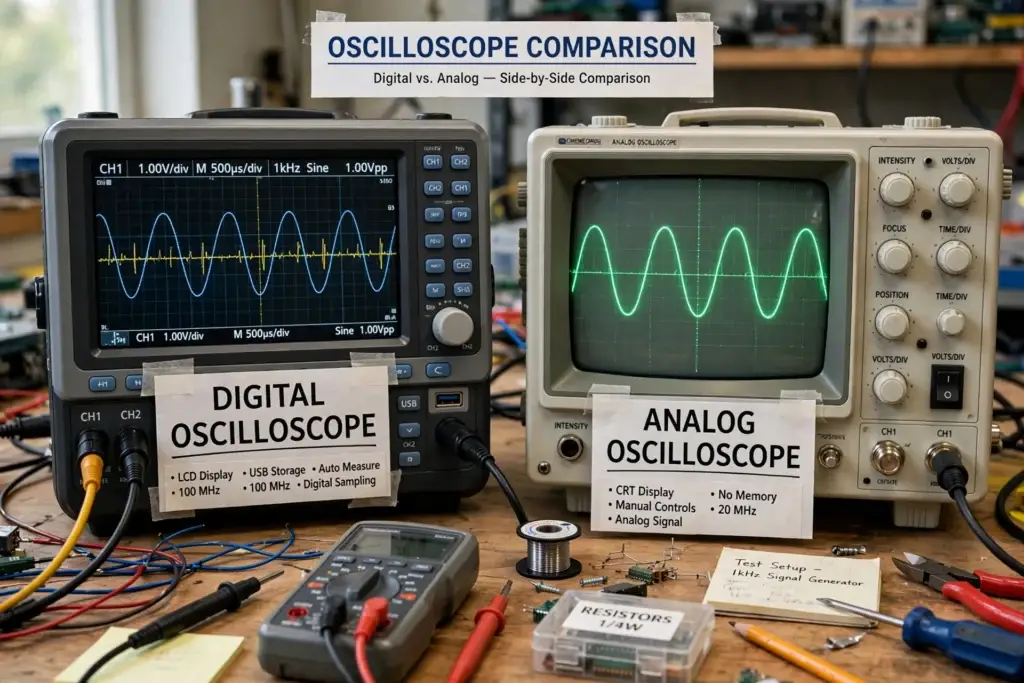
Introduction An oscilloscope is one of the most important instruments for electronics engineers. It allows you to observe electrical signals over time and investigate problems that cannot be diagnosed easily with a digital multimeter alone. Whether you are a hobbyist building electronic circuits, an embedded engineer debugging a microcontroller, or a professional working in an […]
PCB EMI 문제 해결: 전자기 소음을 찾고 줄이는 방법
Electromagnetic interference, or EMI, is one of the most common problems engineers encounter when developing electronic and industrial control systems. A PCB may work perfectly on the laboratory bench but begin to experience communication errors, unexpected resets, sensor noise, or intermittent operation after it is installed inside a machine. Why does this happen? The problem […]
PCB 접지 설계: 노이즈, EMI 및 접지 반사 감소 방법
Introduction One of the most important parts of PCB design is also one of the most frequently misunderstood: Ground. Many engineers initially think of ground as simply a connection to 0 V. In a real PCB, however, ground is also a current-return path. When current flows through a PCB trace, plane, via, connector, or cable, the resistance […]
PCB 전원 문제 해결 방법: 단계별 엔지니어링 방법
Introduction Many electronic problems appear to be software or communication issues. Examples: MCU does not start Communication errors Random reset Sensor malfunction Flash programming failure Industrial controller stop Vision system error However, in many cases, the root cause is: Power quality problem Before replacing ICs or changing software, engineers should first verify: Input […]
PCB Power Integrity: How to Measure VCC Ripple, Noise, and Voltage Drop
Introduction A PCB may appear to have a stable power supply when measured with a multimeter. For example, you may measure: VCC = 3.30 V But this does not necessarily mean that the power rail is clean. An oscilloscope may reveal: Ripple High-frequency noise Voltage spikes Ringing Startup disturbances Voltage drop during high-current operation Switching […]
PCB Trace Width and Current Calculation: A Practical Guide
When designing a PCB, one of the most common questions is: How wide should a PCB trace be for a given current? For example: Can a 0.25 mm trace carry 1 A? Is a 0.5 mm trace enough for 2 A? How wide should a 5 A power trace be? Does 2 oz copper allow […]
PCB Ground Plane: Why It Matters for Signal Integrity and Power Stability
When designing a PCB, engineers often spend a lot of time thinking about signal traces and power traces. However, there is another path that is equally important: The return current path. A signal does not simply travel from one component to another and disappear. Current must complete a loop. For many PCB designs, a properly […]
How to Design a PCB Power Supply Section
A reliable PCB starts with a reliable power supply. Many electronic circuits may appear to work correctly during normal operation but become unstable when the power supply is poorly designed. Problems such as: MCU resets communication errors unstable digital signals unexpected shutdowns Flash programming failures excessive noise component overheating can all be related to power […]
My First PCB Project with Autodesk Fusion: From Schematic to Manufacturing
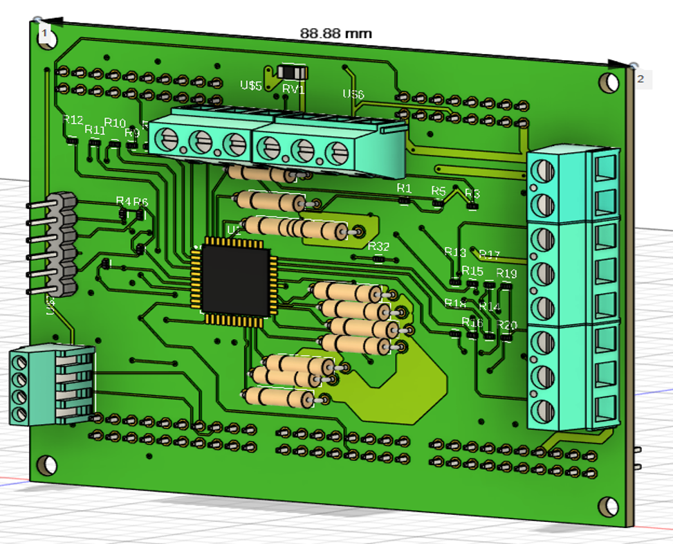
Designing a PCB is much more than drawing copper traces. A complete PCB development process normally includes: Requirements → Schematic → Components → PCB Layout → DRC → 3D Verification → Manufacturing Data → Prototype → Testing Autodesk Fusion Electronics connects the schematic, 2D PCB, and 3D PCB within its electronics design workflow. This article […]
KiCad vs Autodesk Fusion: Which PCB Design Software Is Right for Your Project?

Choosing the right PCB design software can have a major impact on an electronics development project. For a hobby project, you may want software that is free and relatively easy to learn. For a small engineering company, however, PCB layout is only part of the development process. Mechanical design, enclosure dimensions, component placement, manufacturing, and […]