Designing a high-speed LED strobe controller requires more than simply turning an LED on and off.
When an LED must be switched at high speed and synchronized with an external system, the controller needs accurate timing, fast digital logic, stable power, appropriate switching devices, and careful signal-integrity design.
In one of my real-world engineering projects, I developed a high-speed LED strobe controller using an NXP MPC5744P microcontroller, Lattice CPLD, TFT display, and a high-speed line-driver/switching device.
This article explains the system architecture, the reason for dividing the processing between the MCU and CPLD, and some of the important engineering considerations involved in high-speed LED strobe control.
Note: This article describes the engineering architecture and design concepts of the project. Specific proprietary circuit values, firmware details, and customer-specific information are intentionally omitted.
1. What Is an LED Strobe Controller?
An LED strobe controller generates precisely controlled light pulses rather than continuously illuminating an LED.
A typical strobe signal can be described by several parameters:
-
- Frequency
-
- Pulse width
-
- Duty cycle
-
- Trigger timing
-
- Delay
-
- LED current
-
- Rise time
-
- Fall time
For example, a controller may generate a short LED pulse every time an external trigger arrives.
This type of system can be useful for:
-
- Machine vision
-
- Industrial inspection
-
- High-speed cameras
-
- Optical measurement
-
- Manufacturing inspection
-
- Motion analysis
-
- Automated inspection systems
The objective is not simply to generate light.
The objective is to generate the right amount of light at the right time with repeatable timing.
2. Overall System Architecture
The controller was designed around several major functional blocks:
-
- NXP MPC5744P MCU
-
- Lattice CPLD
-
- TFT display
-
- High-speed line-driver/switching stage
-
- LED strobe output
-
- Power supply
-
- External trigger/control interface
A simplified architecture is shown below.
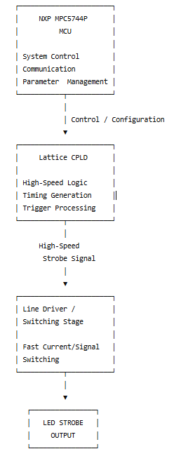
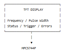
The important design concept is the separation between system-level control and high-speed deterministic logic.
3. Why Use an MCU and CPLD Together?
One of the most important architectural decisions was using both an MCU and a CPLD.
The two devices have different strengths.
NXP MPC5744P
The MPC5744P was used for system-level functions such as:
-
- Overall system control
-
- Parameter management
-
- Communication
-
- User-interface control
-
- System monitoring
-
- Error handling
-
- Configuration management
The MCU is well suited for managing the overall operation of the controller.
However, high-speed strobe generation may require highly deterministic timing.
This is where the CPLD becomes useful.
Lattice CPLD
The Lattice CPLD was used for high-speed digital logic and timing-related functions.
A CPLD can implement hardware logic with predictable timing without relying on software execution paths.
This provides an important architectural advantage:
The MCU controls the system, while the CPLD handles time-critical digital logic.
This division can simplify firmware and improve timing consistency.
4. High-Speed LED Strobe Generation
A simple LED controller could use an MCU GPIO to turn an LED on and off.
However, this approach can become challenging when precise timing and fast response are required.
Software execution can be affected by:
-
- Interrupts
-
- Communication processing
-
- Other firmware tasks
-
- Peripheral activity
-
- Scheduling
-
- System status processing
A hardware-based timing implementation can provide more deterministic behavior.
The CPLD can receive a trigger and generate the required strobe pulse.
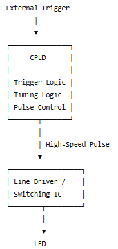
The actual implementation depends on the required frequency, pulse width, LED current, load characteristics, and system interface.
5. The Role of the Line Driver / Switching IC
The digital signal generated by the CPLD may not be sufficient to directly drive the LED load.
A high-speed line-driver or switching stage provides the electrical interface between the digital logic and the LED system.
The switching device must be selected according to requirements such as:
-
- Operating voltage
-
- Output current
-
- Switching frequency
-
- Rise time
-
- Fall time
-
- Power dissipation
-
- Load characteristics
-
- Thermal requirements
An important design concept is:
The logic signal and the LED power signal are not the same thing.
The CPLD generates the control signal, while the switching stage handles the electrical requirements of the LED load.
6. Why Switching Speed Matters
For a high-speed strobe application, the LED pulse is often intentionally short.
If the switching device has a slow rise or fall time, the actual LED pulse may not match the intended waveform.
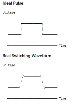
The real waveform may contain:
-
- Rise-time delay
-
- Fall-time delay
-
- Overshoot
-
- Undershoot
-
- Ringing
-
- Ground bounce
Therefore, the actual switching waveform should be measured rather than assumed.
7. TFT Display and User Interface
The TFT display provides a convenient interface between the controller and the operator.
Depending on the system requirements, the display can show:
-
- Strobe frequency
-
- Pulse width
-
- Trigger mode
-
- Output status
-
- System status
-
- Error conditions
-
- Temperature
-
- Communication status
A display is particularly useful in industrial equipment because technicians can verify operating conditions without connecting an external development tool.
The MPC5744P manages the system-level interface, while the CPLD performs the time-critical logic.
8. High-Speed Signal Integrity
High-speed digital switching creates another important engineering challenge: signal integrity.
When a signal changes rapidly, PCB traces can no longer be treated simply as ideal wires.
Important considerations include:
-
- Trace length
-
- Ground-return path
-
- Impedance
-
- Crosstalk
-
- Termination
-
- Connector characteristics
-
- Power-supply noise
-
- Ground bounce
-
- Switching current
A PCB layout that works correctly at low speed may not necessarily work reliably at high speed.
A poor layout can result in:
-
- Signal distortion
-
- False triggering
-
- Overshoot
-
- Ringing
-
- EMI
-
- Timing errors
Therefore, high-speed signal integrity should be considered during the schematic and PCB design stages, not only during troubleshooting.
9. Power Supply Design
The LED switching stage can create significant transient current.
When the LED load switches rapidly, the power-distribution network must respond to the changing current.
This can create:
-
- Supply-voltage ripple
-
- Ground noise
-
- Voltage spikes
-
- EMI
-
- Digital-logic disturbances
The MCU and CPLD may be sensitive to these disturbances.
Therefore, the design should carefully consider power distribution and decoupling for:
-
- MPC5744P
-
- CPLD
-
- TFT display
-
- Digital logic
-
- Line-driver IC
-
- LED power stage
The exact power architecture depends on the electrical requirements of the system.
10. Oscilloscope Verification
One of the most important parts of developing a high-speed strobe controller is measuring the actual waveform.
A digital multimeter is useful for checking DC voltage, but it cannot show a short-duration high-speed switching event.
An oscilloscope is much more useful for analyzing:
-
- Frequency
-
- Pulse width
-
- Duty cycle
-
- Rise time
-
- Fall time
-
- Overshoot
-
- Undershoot
-
- Ringing
-
- Trigger delay
-
- Supply ripple
A useful measurement sequence is:
Trigger Input
      │
      ▼
CPLD Output
      │
      ▼
Line Driver Input
      │
      ▼
Line Driver Output
      │
      ▼
LED Strobe
Comparing the waveform at each stage can help identify where timing distortion or signal degradation occurs.
11. Trigger Synchronization
Trigger timing is particularly important in machine-vision applications.
Consider a camera observing a moving object.
If the LED pulse occurs too early or too late, the resulting image may have:
-
- Motion blur
-
- Incorrect exposure
-
- Inconsistent brightness
-
- Image-to-image variation
Therefore, the timing relationship between the external trigger, LED pulse, and camera exposure can be critical.
A hardware-based timing architecture can provide more predictable behavior.
This is one reason a CPLD can be useful when timing repeatability is important.
12. Troubleshooting a High-Speed Strobe System
When the LED strobe does not operate correctly, troubleshooting should be performed systematically.
Step 1 — Check the Power Supply
Measure:
-
- Input voltage
-
- Logic supply voltage
-
- LED supply voltage
-
- Ripple
-
- Startup behavior
Step 2 — Check the Trigger
Verify that the trigger signal reaches the expected input.
Step 3 — Check the CPLD Output
Use an oscilloscope to verify:
-
- Frequency
-
- Pulse width
-
- Voltage level
-
- Timing
Step 4 — Check the Line Driver
Compare the input and output waveforms.
Step 5 — Check the LED Load
Verify the actual LED current and output waveform.
Step 6 — Check Grounding and PCB Layout
If the signal looks unstable, investigate:
-
- Ground paths
-
- Decoupling
-
- Return current
-
- PCB routing
-
- Connector wiring
-
- Switching noise
This systematic approach is generally more effective than replacing components randomly.
13. Real-World Engineering Experience
This project reinforced an important engineering principle:
High-speed system performance depends on the entire signal path, not just the processor.
The MCU, CPLD, switching device, PCB, power supply, connectors, and LED load all interact with one another.
A processor may be capable of generating a fast signal, but the final system performance can still be limited by:
-
- Switching-device characteristics
-
- PCB layout
-
- Power distribution
-
- Grounding
-
- Load characteristics
-
- Signal integrity
This is why high-speed hardware development requires both digital logic knowledge and electrical signal-integrity analysis.
Real system examples : Free running mode, Encored running mode
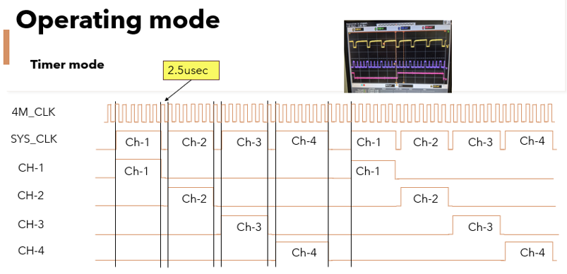
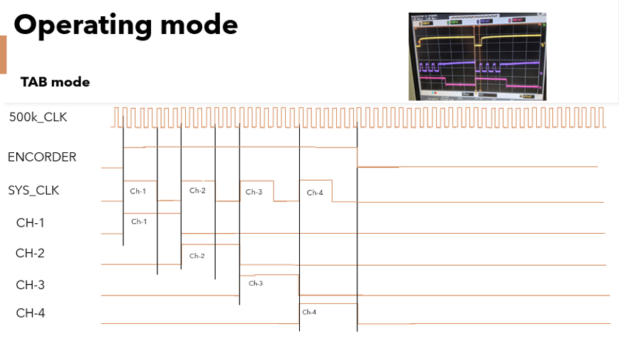
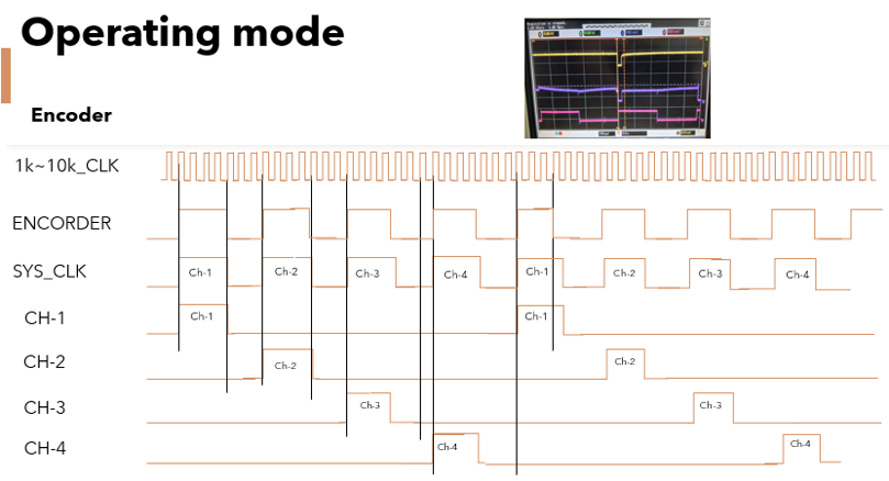
Recommended major parts;
- CSD18502KCS (MOSFET – Texas Instruments)
- FOD0721 (Optocoupler – onsemi)
- MPC 5744P
- ISPLSI2032
14. Lessons Learned
Several important lessons from this project can be applied to other embedded hardware designs.
1. Divide the architecture by function
Use the MCU for system management and the CPLD for deterministic high-speed logic when appropriate.
2. Measure actual waveforms
Do not assume that the signal at the source is the same as the signal at the load.
3. Consider power integrity
High-speed switching can affect the power supply and digital logic.
4. Design the PCB for the signal
Signal integrity should be considered during PCB design, not only during troubleshooting.
5. Validate the complete system
Final verification should include:
-
- MCU
-
- CPLD
-
- Line-driver/switching IC
-
- Power supply
-
- LED load
-
- Trigger source
-
- TFT display
-
- Communication interface
Conclusion
A high-speed LED strobe controller is a good example of a system where embedded software, programmable logic, power electronics, and high-speed signal integrity must work together.
In this project, the NXP MPC5744P provided system-level control, the Lattice CPLD handled high-speed deterministic logic, the TFT display provided operator control and monitoring, and the line-driver/switching stage connected the digital control system to the LED output.
The most important lesson is that high-speed performance cannot be evaluated from a schematic alone.
The actual waveform must be measured.
By combining an appropriate system architecture with careful PCB design, power integrity, switching-device selection, and oscilloscope verification, engineers can develop more reliable high-speed LED strobe systems.
Recommended Engineering Tools
For developing and troubleshooting a high-speed LED strobe controller, useful tools include:
-
- Oscilloscope
-
- Logic analyzer
-
- Digital multimeter
-
- Programmable power supply
-
- Electronic load
-
- Current probe
-
- PCB design software
2 Responses