How to Troubleshoot PCB Power Problems: A Step-by-Step Engineering Method
Introduction Many electronic problems appear to be software or communication issues. Examples: MCU does not start Communication errors Random reset Sensor malfunction Flash programming failure Industrial controller stop Vision system error However, in many cases, the root cause is: Power quality problem Before replacing ICs or changing software, engineers should first verify: Input […]
PCB Power Integrity: How to Measure VCC Ripple, Noise, and Voltage Drop
Introduction A PCB may appear to have a stable power supply when measured with a multimeter. For example, you may measure: VCC = 3.30 V But this does not necessarily mean that the power rail is clean. An oscilloscope may reveal: Ripple High-frequency noise Voltage spikes Ringing Startup disturbances Voltage drop during high-current operation Switching […]
PCB Trace Width and Current Calculation: A Practical Guide
When designing a PCB, one of the most common questions is: How wide should a PCB trace be for a given current? For example: Can a 0.25 mm trace carry 1 A? Is a 0.5 mm trace enough for 2 A? How wide should a 5 A power trace be? Does 2 oz copper allow […]
PCB Ground Plane: Why It Matters for Signal Integrity and Power Stability
When designing a PCB, engineers often spend a lot of time thinking about signal traces and power traces. However, there is another path that is equally important: The return current path. A signal does not simply travel from one component to another and disappear. Current must complete a loop. For many PCB designs, a properly […]
How to Design a PCB Power Supply Section
A reliable PCB starts with a reliable power supply. Many electronic circuits may appear to work correctly during normal operation but become unstable when the power supply is poorly designed. Problems such as: MCU resets communication errors unstable digital signals unexpected shutdowns Flash programming failures excessive noise component overheating can all be related to power […]
My First PCB Project with Autodesk Fusion: From Schematic to Manufacturing
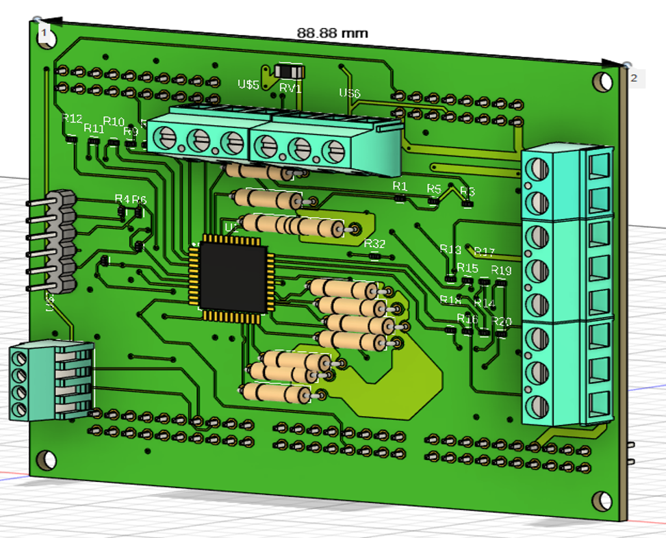
Designing a PCB is much more than drawing copper traces. A complete PCB development process normally includes: Requirements → Schematic → Components → PCB Layout → DRC → 3D Verification → Manufacturing Data → Prototype → Testing Autodesk Fusion Electronics connects the schematic, 2D PCB, and 3D PCB within its electronics design workflow. This article […]
KiCad vs Autodesk Fusion: Which PCB Design Software Is Right for Your Project?

Choosing the right PCB design software can have a major impact on an electronics development project. For a hobby project, you may want software that is free and relatively easy to learn. For a small engineering company, however, PCB layout is only part of the development process. Mechanical design, enclosure dimensions, component placement, manufacturing, and […]
PCB Design Software for Small Businesses and Personal Projects: KiCad, Autodesk Fusion, and More
Designing a PCB is no longer limited to large engineering companies with expensive EDA software. Today, individual engineers, students, makers, startups, and small engineering companies can design professional PCBs using a variety of tools. The important question is: Which PCB design software is appropriate for a small company or an individual engineering project? There is […]
CR2032 Battery Design: Battery Life, Voltage Stability, and Flash Programming Errors
A CR2032 coin-cell battery is widely used in compact and handheld electronic devices because of its small size, low cost, and relatively long operating life. However, designing a device around a CR2032 battery requires more than simply calculating how long the battery will last. Two important design considerations are: A device may continue to operate […]
RS-485 Termination and Bias Resistor: Practical Calculation and Troubleshooting
RS-485 is widely used in industrial automation systems to connect PLCs, robots, PCs, remote I/O, sensors, and controllers. Although RS-485 is designed for reliable differential communication, incorrect termination, biasing, wiring, or grounding can cause intermittent communication problems. This article explains how to calculate the termination and bias resistors in a practical RS-485 network. 1. Basic […]