Introduction
A digital signal is normally expected to remain in a stable state between HIGH and LOW. Digital circuits use these two defined voltage levels to process and transmit information reliably.
However, a digital signal can sometimes enter an undefined or unstable state, especially when the power supply is not stable.
This problem can occur during power-on, sudden changes in load current, or situations where a circuit requires a high amount of current.
What Is a Stable Digital Signal?
In a typical digital circuit, a signal is interpreted as either:
- HIGH (Logic 1)
- LOW (Logic 0)
For reliable operation, the voltage should remain within the specified HIGH or LOW voltage range.
For example:
HIGH ─────────────────────
│
│
LOW ────────────────────
The transition between HIGH and LOW should occur cleanly and quickly.
If the voltage remains in an uncertain region, the receiving device may not reliably determine whether the signal represents a HIGH or LOW.
Why Can a Digital Signal Become Unstable?
One important cause is an unstable power supply.
During power-on, for example, the power supply voltage may take some time to reach its normal operating level.
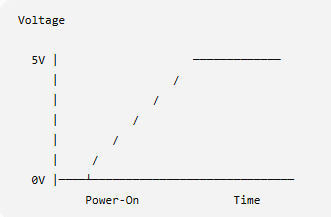
During this period, the digital circuit may not be operating under normal conditions.
Another situation occurs when the circuit suddenly requires a large amount of current.
When the load current increases rapidly, the power supply voltage can temporarily drop. This is sometimes called a voltage dip or voltage droop.
Real-World Engineering Experience: Power Reset and Boot-Up Stability
During the development of a main controller unit, I encountered an intermittent startup problem caused by an unstable power reset signal.
Under certain unstable power input conditions, the power reset signal was not stable enough, causing the controller unit to fail to start properly. The problem was especially noticeable during abnormal or unstable power conditions.
To improve the startup reliability, I modified the power reset circuit to provide a more stable reset signal. I also modified the control signals used during the boot-up sequence and configured the appropriate signals with pull-up resistors to ensure that they maintained a defined logic state during power-up.
After these changes, the controller was able to maintain more reliable logic states during the power-on and boot-up sequence, reducing startup failures caused by unstable power input.
This experience demonstrated an important principle in digital hardware design:
A stable power supply and well-defined reset and control signals are essential for reliable system startup.
Unstable Power Input
↓
Power Supply Voltage Fluctuation
↓
Unstable Reset Signal
↓
Undefined Logic State
↓
Controller Boot Failure
↓
Improved Reset Circuit + Pull-Up Control Signals
↓
Stable Boot-Up
High Current Can Affect Digital Signals
Consider a digital system containing a processor, memory, communication circuits, and other devices.
When several devices start operating simultaneously, the current demand can increase significantly.
If the power supply or PCB power distribution cannot respond quickly enough, the supply voltage may temporarily decrease.
This can affect:
- Microprocessors
- Microcontrollers
- Memory devices
- Communication interfaces
- Logic gates
- Sensors
- FPGA systems
As a result, digital signals may become unstable or behave unexpectedly.
What Happens When the Signal Is in an Undefined Region?
Digital inputs normally have specified voltage thresholds.
For example:
    HIGH
   ─────────────
        ↑
   HIGH threshold
   ─────────────
   Undefined
   ─────────────
   LOW threshold
        ↓
   ─────────────
    LOW
If the input voltage stays between the LOW and HIGH thresholds, the receiving device may not reliably recognize the signal.
This can potentially result in:
- Incorrect logic operation
- Unexpected switching
- Communication errors
- Processor malfunction
- System resets
- Intermittent failures
These problems can be particularly difficult to troubleshoot because the system may work normally under
ome conditions but fail when the load changes.
How Can We Improve Power Stability?
Several design techniques can help reduce these problems.
1. Proper power supply design
The power supply should provide sufficient voltage and current for the entire system.
2. Decoupling capacitors
Place appropriate decoupling capacitors close to IC power pins to reduce short-duration voltage fluctuations.
3. Adequate PCB power and ground design
Power and ground traces should be designed to minimize voltage drop and noise.
4. Power sequencing
For systems containing multiple voltage rails, the correct power-up and power-down sequence may be important.
5. Brownout and reset protection
A reset circuit or brownout detection can prevent the processor from operating when the supply voltage is below a safe level.
6. Measure the signal during actual operation
An oscilloscope can be very useful for identifying power-related digital signal problems.
Instead of measuring only the DC voltage with a multimeter, check the power rail and digital signal with an oscilloscope during:
- Power-on
- Power-off
- High-current operation
- Communication activity
- Sudden load changes
Conclusion
Digital signals are expected to operate between well-defined HIGH and LOW states. However, unstable power conditions can cause unexpected or undefined signal behavior.
Power-on conditions and sudden high-current demand are two situations that should receive particular attention during hardware design and troubleshooting.
A stable digital system requires more than simply generating the correct logic signals. The power supply, PCB layout, grounding, decoupling, and reset design all contribute to reliable digital operation.
2 Responses